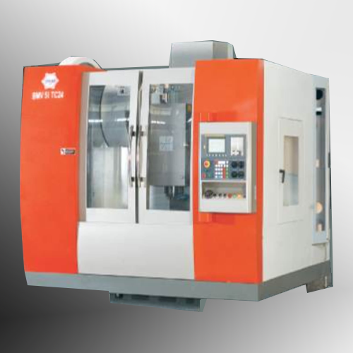
MACHINING

MACHINING CONSIDERATIONS
MACHINE FINISH ALLOWANCES
When machining castings, it is always advisable to discuss with the foundry the method of machining and the locations to be used as datums for each operation. As will be seen on the notes regarding tolerances, the dimensional relationship between different areas on a casting varies according to the die and mould construction.
The need for a Machining and die designer to co-operate cannot be over emphasised. Frequently, the cost of finished castings can be significantly reduced by arranging for casting feeders to be located on areas which are to be machined. This minimises the need for fettling, and eliminates the feeder witnesses on the finished component.
Below is a table showing the amount of metal normally added for machining. The amount of material to be added is related to the overall size of the casting, rather than varying with individual dimensions. The designer should select that line on the table below showing the range within which the casting's greatest dimension falls.
| GREATEST DIMENSION | SAND CAST | GRAVITY DIE CAST WITH SAND CORES | GRAVITY DIE CAST | PRESSURE DIE CAST |
|---|---|---|---|---|
| less than 150mm | 1.5 | 1.5 | 1.125 | .0.375 |
| 150-300mm | 2.25 | .2.25 | .1.5 | 0.5 |
| 300-450mm | 3.0 | 3.0 | 1.875 | 0.625 |
| 450-600mm | 3.75 | 4.5 | 2.25 | 0.75 |
The values given in the above table are based on maximum 'build-up' or a 'safety factor' for average casting variations in flatness, squareness, concentricity, etc., as well as linear tolerance. The values are the minimum recommended, and taper, when required, must be added to the above values.
Download
Order Product